

Industry News
A start switch, a stop switch, control three-phase motor, how to connect?
Views : 14872
Author : HBAN PUSH BUTTON SWITCH
Update time : 2022-08-20 11:56:52
A start switch, a stop switch, control three- phase motor, how to connect? To be honest, I've been an electrician for 30 times, and I really have not taken over the start- stop circuit of a three- phase motor using a start switch and a stop switch. It's also possible that I'm too hard on the word, and the AC contactor isn't mentioned in the title. else, I really do not know how to wireit.However, also it'll be different, If there's an AC contactor and a thermal relay. The route for the thermal relay and AC contactor to control the start and stop of the motor is fairly simple, and it's one of the introductory chops that the staff who have just started the electrical assiduity mustmaster.However, the first step is to understand the introductory principles of circuits, If you want to learn how to connect cables well. To understand the introductory principles of circuits, you must first learn to understand simple circuit schematics. The electrical schematic illustration of a start switch, a stop switch, an AC contactor, and a thermal relay is shown in the following figure
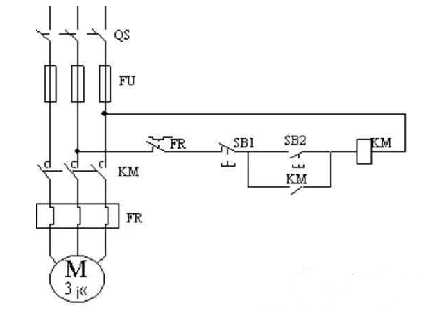
In the figure, SB1 is the stop switch, SB2 is the start switch, KM AC contactor, FR thermal relay, FU fuse. The control principle is as follows, press the start switch SB2, the AC contactor coil KM □ is amped and closed, and at the same time the KM,/, typically open connections are closed, the AC contactor completes tone- locking, and the motor starts to work. Press the stop switch SB1, if the control route is disconnected, the motor stops rotating.
The wiring system is as follows
Connect a control line from C to one end of the AC contactor coil( A1);
Connect a line from the other end of the coil( A2) to the upper end of the typically open contact of the AC contactor;
At the same time, connect a line from the typically open contact to the typically open contact of the start switch;
Connect a line from below the typically open contact of the start switch to the other end of the typically open contact of the AC contactor;
At the same time, draw a line from the supplementary typically open contact of the AC contactor to the typically closed contact of the stop switch;
Connect a line from the other end of the typically closed contact of the stop switch to the supplementary typically closed contact of the thermal relay;
The other end of the thermal relay typically closed contact leads out a line to connect to theA-phase or B- phase of the three- phase power force. At this point, a simple three- phase motor control route is completed.
Related News
Read More >>
 What is ISO 13850?| HBAN Push button
Jul .15.2026
EN ISO 13850 defines the design principles of the emergency stop function for machinery operating in the European Union. For manufacturers targeting the German and EU markets, compliance with this standard is essential for CE marking, machine safety appro
 How to Choose the Right Push Button Switch for Panel Thickness | HBAN Push button
Jun .23.2026
Choosing the correct push button switch requires matching thread length to panel thickness. This guide explains how to measure, calculate, and select the right model to prevent installation problems and ensure secure mounting.
 How to Choose IP65, IP67 & IP69K?| HBAN Push button
Jun .15.2026
This article outlines the fundamentals of the IP rating system and analyzes how dust and water protection levels directly affect the reliability, safety, and service life of push button switches in industrial environments.
 Industrial Push Button IEC 60947-5-1 vs IEC 60947-5-5 | HBAN Push button
May .21.2026
Industrial push button IEC 60947-5-1 compliant devices are designed for reliable operation in industrial control circuits. They meet international standards for rated voltage, current, AC-15 and DC-13 utilization categories, and mechanical endurance. Wide